From Substrate to Service Life
Titanium anodes, also known as mixed metal oxide (MMO) anodes or dimensionally stable anodes (DSA), are electrochemical electrodes made of a titanium substrate coated with a thin catalytic layer of precious metal oxides. The common coating systems are based on ruthenium and iridium oxides, iridium and tantalum oxides, or platinum. Since DSA technology was first commercialized for the chlor-alkali industry in the late 1960s, coated titanium anodes have steadily replaced lead, graphite, and other anode materials in electroplating, water treatment, electrowinning, cathodic protection, and many other electrochemical processes.
This guide is written for engineers, plant operators, and purchasing professionals who specify, buy, or operate coated titanium anodes. the starting point for the subject on this site: each chapter gives you the working knowledge, then points to a companion article where we go deeper. It answers three practical questions:
- How MMO titanium anodes are manufactured, from substrate selection and surface preparation through coating application and quality testing;
- How to select the right anode by matching the coating system, substrate geometry, and coating loading to the electrochemical reaction and operating conditions;
- How to maintain anodes in service so they reach their design life with minimum downtime and the lowest total cost of ownership.
Key takeaways
- Match the coating family to the reaction: ruthenium-based for chlorine evolution, iridium-based for oxygen evolution.
- Specify loading in the range of 5 to 50 g/m² and validate it with accelerated life test data.
- Watch cell voltage trends and clean gently. Recoat early rather than replace late.
1. What Is a Titanium Anode?
1.1 Definition and Working Principle
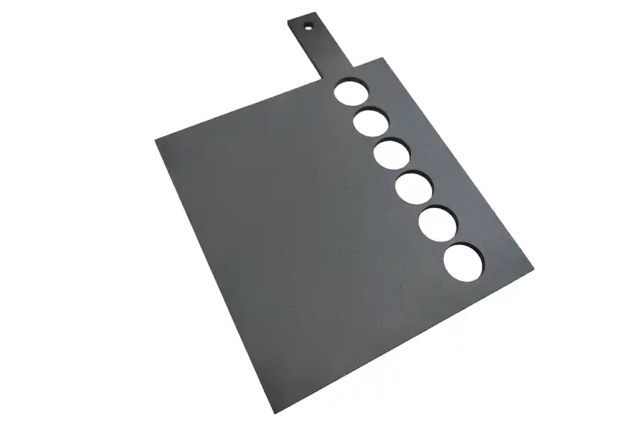
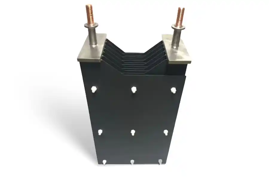
A titanium anode is an insoluble anode built from two functional parts: a titanium base metal that carries the current and gives the anode its shape, and a thin electrocatalytic coating on the working surface that does the actual electrochemical work. The coating is typically only a few micrometers thick, yet it decides the reaction, the cell voltage, and the service life.
Titanium on its own is a poor anode. It belongs to the valve metals, which means it grows a dense, non-conductive oxide film as soon as it is polarized anodically. That film protects the metal from corrosion but also blocks current. The catalytic coating solves the contradiction: it conducts electrons into the electrolyte and lowers the energy needed for the target reaction, while the passive film underneath keeps the substrate sealed wherever the coating is thin or damaged. This is why a coated titanium anode fails gradually as the coating wears, instead of dissolving at the first defect the way a graphite or lead anode does.
Compared with the older anode materials it replaces, a coated titanium anode brings three practical advantages: dimensional stability over years of service, lower cell voltage through reduced overpotential, and no contamination of the electrolyte by anode corrosion products.
1.2 MMO and DSA: Two Names for the Same Family
Two terms dominate quotations and datasheets, and they refer to the same product family. DSA, dimensionally stable anode, is the historical term from the chlor-alkali industry of the late 1960s, coined when coated titanium anodes replaced eroding graphite and held their geometry for years. MMO, mixed metal oxide, is the materials term: the coating is a blend of precious metal oxides, most commonly RuO₂ or IrO₂, with valve metal oxides such as TiO₂ or Ta₂O₅ that stabilize the film and bond it to the substrate. If a datasheet says DSA type, expect a ruthenium or iridium-based oxide coating on titanium. Platinized titanium and PbO₂ on titanium are related coated anodes usually referred to by their own names. For definitions of the terms used across this guide, see our titanium anode technical glossary, and for a product level introduction see coated titanium anodes.
1.3 Structure: Substrate, Interface, Coating
Every titanium anode is built from three functional layers:
- Substrate. Commercially pure titanium, supplied as plate, sheet, expanded mesh, tube, rod, wire, or ribbon. It carries the current and defines the geometry.
- Interface layer. A conditioned surface zone created by blasting or etching, giving the top coating a uniform anchor profile and slowing the growth of the insulating oxide film at the boundary.
- Active coating. The MMO, platinum, or PbO₂ layer where the anodic reaction takes place. This is the consumable part of the anode, and the part that recoating renews.
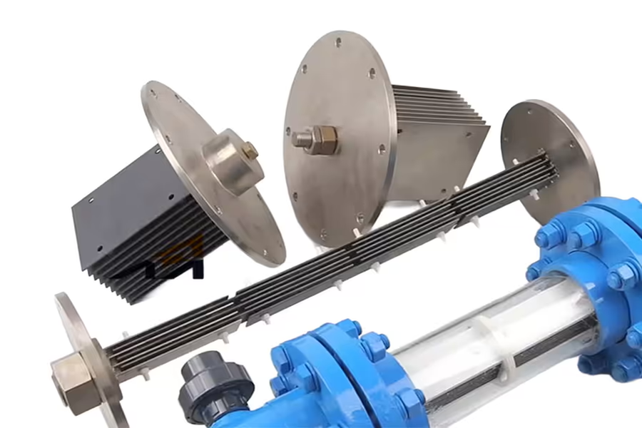
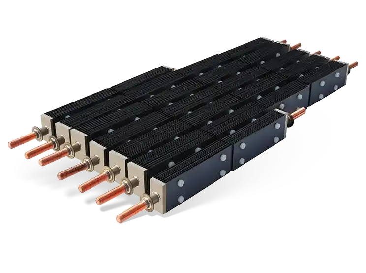
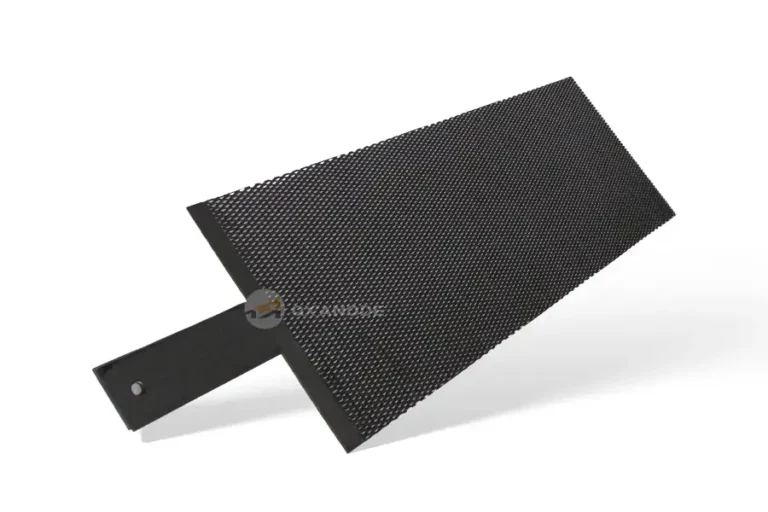
Geometry is a working variable, not a cosmetic one. Expanded mesh suits cells that need high area and good electrolyte circulation, plate and sheet serve tanks and impressed current systems, tubular and wire forms dominate cathodic protection, and baskets fit plating lines. The substrate material itself is covered in detail in our article on titanium and titanium alloy mill products.
2. CER vs OER: The Reaction That Selects the Coating
Almost every coating decision reduces to one question: does your anode evolve chlorine or oxygen?
The chlorine evolution reaction (CER) runs in chloride-containing electrolytes: chloride ions discharge to chlorine gas at the anode. It is the working reaction of chlor-alkali production, sodium hypochlorite generation, and seawater electrochlorination. The oxygen evolution reaction (OER) runs where water is oxidized instead, releasing oxygen and acid. It dominates in sulfate electrolytes, dilute acids, most electrowinning baths, and electro-oxidation water treatment.
The two reactions compete whenever both chloride and water are present, and the coating tips the balance. Ruthenium-based coatings have the lowest chlorine overpotential and are the standard for CER duty. Iridium-based coatings resist oxidative dissolution and are the standard for OER duty. Each fails fast in the other’s service: a ruthenium coating under sustained oxygen evolution oxidizes toward soluble higher oxides, while an iridium coating in brine carries a higher chlorine overpotential with no benefit in return.
| CER duty (chlorine) | OER duty (oxygen) | |
|---|---|---|
| Electrolyte signature | High chloride: brine, seawater, hydrochloric systems | Low or zero chloride: sulfate, nitrate, acid, natural waters |
| Preferred coating | RuO₂ based MMO (Ru-Ir) | IrO₂ based MMO (Ir-Ta), or PbO₂ for special oxidations |
| Wrong coating consequence | Higher chlorine overpotential, wasted power | Rapid dissolution of RuO₂, life measured in weeks |
Borderline cases need care. Seawater electrochlorination runs at moderate chloride with significant oxygen co-evolution, so seawater grade Ru-Ir formulations are tuned for selectivity. Industrial effluents carrying both chloride and organics demand a coating that survives both. If your electrolyte does not fit neatly into one column, share the full analysis with the anode maker, including seasonal variation, and ask for a formulation recommendation in writing. The two coating families are introduced in detail in our articles on the Ru-Ir coated titanium anode and the iridium-tantalum coated titanium anode.
3. Titanium Anode Manufacturing and Processing
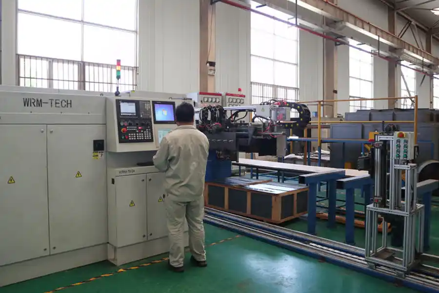
A coated titanium anode earns its performance in the factory. Substrate selection, surface preparation, coating formulation, thermal treatment, and quality testing each have a direct effect on current efficiency, service life, and batch-to-batch consistency. This chapter focuses on the specification and quality side that buyers should verify; for the full production sequence as it runs on our line, see Titanium Anode Manufacturing.
3.1 Substrate Selection and Material Standards
The titanium substrate does three jobs: it carries the current, it holds the coating, and it resists corrosion in the electrolyte. Commercially pure titanium is used almost exclusively because it forms a thin, self-healing oxide film that holds up well in oxidizing media.
- Grade 1 titanium: the softest and most formable grade, used where deep forming is required and maximum corrosion resistance matters more than strength.
- Grade 2 titanium: the standard choice for MMO anodes. It is stronger than Grade 1 with the same corrosion resistance, and it suits plates, mesh, rods, tubes, and baskets.
- Grade 7 and Grade 11 titanium: palladium bearing grades for reducing acid environments where unalloyed titanium may corrode.
Material is normally purchased to recognized standards such as ASTM B265 (titanium strip, sheet, and plate) and ASTM B348 (titanium bars and billets). Ask for mill certificates for every heat to confirm chemical composition, mechanical properties, and traceability, because minor impurities such as iron, oxygen, and carbon affect both corrosion resistance and weldability.
3.2 Substrate Fabrication and Surface Preparation
The substrate is first fabricated into its final working shape (plate, expanded mesh, rod, tube, wire, or basket) by cutting, rolling, forming, and welding. Connections such as copper-titanium clad bars, threaded lugs, or welded studs are added at this stage. TIG (argon arc) welding is preferred because it preserves corrosion resistance and avoids embrittlement at the joint.
Surface preparation is the most critical step before coating. The catalytic layer bonds reliably only to a clean surface with the right roughness profile. A typical preparation sequence:
- Degreasing to remove oils, grease, and process fluids;
- Mechanical blasting, for example with alumina grit, to remove the native oxide layer, expose fresh metal, and create a uniform anchor profile for the coating;
- Acid pickling or etching, commonly in a hydrofluoric and nitric acid mixture, to remove residual oxide, contaminants, and embedded grit;
- Final rinsing and drying, followed by immediate transfer to the coating line to prevent re-oxidation.
Inconsistent surface preparation is one of the most common root causes of premature coating detachment in the field.
3.3 Coating Systems and Technology
The MMO coating is applied by thermal decomposition, also called thermal oxidation or firing. Precursor salts such as ruthenium chloride (RuCl₃), chloroiridic acid (H₂IrCl₆), tantalum chloride, and chloroplatinic acid (H₂PtCl₆) are dissolved in a suitable solvent, applied to the prepared substrate in thin layers, and fired at high temperature so the chlorides convert into the corresponding metal oxides.
The four coating families in common use each target a specific electrochemical reaction:
- Ruthenium-based coatings (RuO₂-TiO₂) for chlorine evolution in chloride media: seawater electrochlorination, salt chlorine generators, and chlor-alkali service;
- Iridium-based coatings (IrO₂-Ta₂O₅) for oxygen evolution in acidic sulfate, nitrate, and phosphate electrolytes: electroplating, electrowinning, and electro-oxidation water treatment;
- Platinum-coated titanium (Pt/Ti) where platinum catalysis or product purity is required, such as precision plating and specialized electrochemical cells;
- Lead dioxide (PbO₂) on titanium as a lower cost option for organic oxidation and strong-acid wastewater treatment.
3.4 Coating Application Process Steps
A controlled coating campaign follows these steps, repeated layer by layer until the target loading is reached:
- Precursor preparation: formulate the mixed metal precursor solution at a controlled metal ratio and concentration.
- Application: apply a thin, uniform layer by brush, roller, spray, or dipping, covering only the active area.
- Drying: dry at low temperature to remove the solvent slowly and avoid blistering.
- Thermal decomposition: fire at approximately 400 to 450 °C to convert the precursors into a coherent oxide film.
- Repeat: build up successive layers until the specified precious metal loading, commonly 5 to 50 g/m², is achieved.
- Final inspection: check color uniformity, adhesion, and coating thickness before packing.
Firing temperature, atmosphere, and heating rate must be controlled closely. Too low a temperature leaves organic residue and poor adhesion. Too high a temperature forms non-catalytic crystalline phases and reduces electrochemical activity.
3.5 Coating Loading and Its Effect on Performance
Coating loading is the mass of precious metal oxide per unit of active area, expressed in grams per square meter (g/m²). It is one of the main levers on anode life and cost.
- Higher loading generally extends service life and raises the current density the anode can carry;
- Higher loading increases material cost, because platinum group metals are expensive;
- Under-specifying loading causes premature coating failure and more frequent replacement;
- Over-specifying loading wastes precious metal the process will never consume.
The economic balance point comes from matching the loading to the target service life, the actual current density, and how aggressive the electrolyte is, then validating the choice with accelerated life test data from the manufacturer.
3.6 Quality Control and Testing
Because anode failure usually means process downtime, reputable manufacturers back every batch with a defined quality program, typically under an ISO 9001 quality management system. Key tests include:
- Coating adhesion: tape pull, scratch, or bend tests to confirm the coating will not flake off in service;
- Coating thickness and loading: X-ray fluorescence (XRF) and gravimetric measurement to verify the specified loading and uniform coverage;
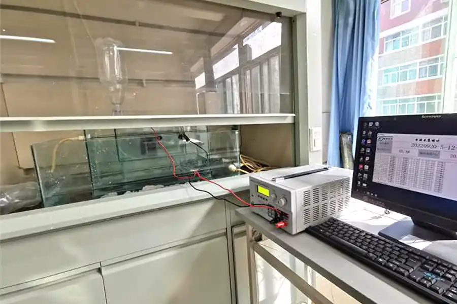
- Electrochemical activity: polarization curves, current efficiency, and chlorine or oxygen evolution potential tests to confirm the coating performs as specified;
- Accelerated life test (ALT): running the anode at high current density in an aggressive electrolyte to estimate service life under accelerated conditions and to compare batch consistency;
- Traceability: batch records, test certificates, and material mill certificates shipped with each order.
3.7 Custom Fabrication and Engineering Support
Industrial anodes are rarely off the shelf. A capable manufacturer supports custom shapes and sizes (plate, expanded mesh, rod, tube, wire, and basket forms), reviews your drawings, advises on coating selection, and issues a documented specification. Look for a supplier with in-house R&D and proven coating formulations, because batch-to-batch coating consistency is the single largest quality variable in this industry.

4. Titanium Anode Selection
Selecting an anode is a specification exercise, not a catalog lookup. The steps below follow the order the decisions should be made, from the electrochemical reaction down to the commercial terms. This chapter works through the reasoning behind each step; if you want a condensed checklist you can paste straight into an RFQ, see How to Choose Coated Titanium Electrodes, which also lists the current density window and relative cost of every coating system in table form.
4.1 Step 1: Determine the Electrochemical Reaction
The first question is what reaction the anode must catalyze:
- Chlorine evolution in chloride media such as seawater, brine, and hydrochloric acid: use ruthenium-based coatings;
- Oxygen evolution in sulfate, nitrate, and phosphate media such as most plating baths, electrowinning, and water treatment: use iridium-based coatings;
- Demanding purity or noble metal catalysis: use platinum-coated titanium.
Getting this first call right matters more than any later refinement. The active oxides dissolve at a reaction they were never formulated for, so a ruthenium coating parked in continuous oxygen-evolving acid service can lose most of its activity in a matter of weeks.
4.2 Step 2: Define the Electrolyte and Operating Conditions
Document the full operating envelope before specifying the anode:
- Electrolyte composition and pH, whether acidic, neutral, or alkaline;
- Operating temperature, since higher temperature speeds up coating consumption;
- Fluoride content: fluoride attacks the titanium substrate, and levels above roughly 20 ppm call for a revised design;
- Current density (A/m²) and duty cycle, whether continuous or intermittent;
- Impurities: heavy metals, organics, and suspended solids affect both coating life and fouling behavior.
Extreme conditions, for example pH below 1, also call for a revised design and a manufacturer review rather than a standard catalog item.
4.3 Step 3: Choose the Coating System
Table 1 summarizes what each coating family is built for and, just as important, what it cannot tolerate. Use it to narrow the field, then check the permitted current density window and cost level for the surviving candidates in our coating system comparison table before you commit.
Table 1. Coating families: what each one drives, and what it will not forgive
| Coating system | Reaction it drives | What it will not tolerate | Where it earns its keep |
|---|---|---|---|
| IrO₂-Ta₂O₅ | Oxygen evolution | Chloride rich service; the tantalum stabilizer is spent on the wrong duty | Strong acid at sustained high current: plating, electrowinning, copper foil |
| RuO₂-TiO₂ (Ru-Ir) | Chlorine evolution | Continuous oxygen evolution in acid; the oxides deactivate several times faster than in chloride duty | Brine, seawater, and chlor-alkali service where chlorine is the product |
| Platinum (Pt/Ti) | Oxygen or chlorine evolution | Processes that do not need platinum grade purity; the cost is hard to justify | Precision and noble metal plating where bath purity decides yield |
| PbO₂ on Ti | Organic oxidation | Electrolytes where any lead release is unacceptable | Strong acid wastewater streams treated for organics on a tight budget |
4.4 Step 4: Select Substrate Geometry and Current Distribution
The working geometry has to deliver a uniform current distribution and fit the cell construction:
- Plate anodes for uniform fields and large flat active areas;
- Expanded mesh anodes for high surface area, better electrolyte flow, and less gas blinding;
- Rod and tube anodes for deep well, tubular, and cathodic protection applications;
- Baskets and racks for electroplating lines and loose fill service.
Geometry, spacing, and shielding all influence current distribution. Poor distribution creates hot spots that consume the coating unevenly and shorten anode life.
4.5 Step 5: Specify Coating Loading and Target Service Life
Agree on a target service life with the manufacturer and specify the corresponding loading. Ask for accelerated life test (ALT) data at your expected current density so the loading decision rests on evidence rather than guesswork. Loading is typically 5 to 50 g/m², with higher values reserved for aggressive service or long design life.
4.6 Step 6: Design the Connection and Installation
The electrical connection is part of the anode system, not an afterthought:
- Use copper-titanium clad bars, welded lugs, or bolted connections sized for the full current;
- Keep connection resistance low to avoid local heating;
- Seal or insulate non-active areas and connections where they would otherwise pass current or corrode;
- Verify polarity and spacing during installation to prevent shorts and stray current.
4.7 Step 7: Qualify the Supplier
For a component that decides process uptime, supplier qualification matters as much as the product itself. Request from any candidate supplier:
- Accelerated life test (ALT) data and the test conditions behind each number;
- Coating adhesion, thickness, and loading certificates for reference batches;
- A written service life warranty and a recoating option;
- ISO 9001 certification and evidence of in-house R&D and coating know-how;
- References from buyers in the same application and market region.
4.8 Application Selection Matrix
Table 2 maps the common application clusters to a coating direction, the geometry that suits the cell, and the loading guidance buyers most often settle on. For the reasoning behind each coating recommendation by application, see the application matching section of our electrode selection guide.
Table 2. Application clusters with geometry and loading guidance
| Application cluster | Coating direction | Geometry that suits it | Loading guidance |
|---|---|---|---|
| Electroplating (decorative and functional) | IrO₂-Ta₂O₅ | Baskets and racks in plating lines | Mid range; a spare set matters more than heavy loading |
| Electrowinning (copper, zinc, nickel) | IrO₂-Ta₂O₅ | Large flat mesh or plate arrays | Upper range; long campaigns between cell openings |
| Seawater and brine electrochlorination | RuO₂-TiO₂ (Ru-Ir) | Tubes in flow channels, mesh in tanks | Mid range; prioritize coating consistency over loading |
| Salt chlorine generators | RuO₂-TiO₂ (Ru-Ir) | Compact mesh cassettes | Match the rated hours of the generator, no more |
| Electro-oxidation wastewater treatment | IrO₂-Ta₂O₅ or PbO₂ | Plate or mesh stacks in open cells | Size to effluent variability, not peak flow alone |
| Cathodic protection (ICCP) | IrO₂-Ta₂O₅ or mixed MMO | Tubular groundbed anodes, wire | High design life; loading is secondary to seal integrity |
| Precision and noble metal plating | Platinum (Pt/Ti) | Small plate, wire, and mesh forms | Thickness specified in microns of platinum, not g/m² |
4.9 Current Density in Practice
Current density, the current per unit of active anode surface, is the single most influential operating parameter for anode life. Most MMO coatings show a life that falls off steeply as current density rises beyond the design point, so an anode run persistently above its specified window can deliver well under half its expected life. Four habits keep this parameter honest:
- Calculate current density on the true active area. For expanded mesh that is the developed surface, not the envelope dimensions, so align on the definition before comparing supplier figures.
- Respect the lower end too. Some coatings wear disproportionately at very low current density because side reactions take a larger share of the current.
- Watch distribution, not just the average. Edges, corners, and connection points see higher local density, and good cell design keeps peak values inside the comfort zone of the coating.
- When reviewing a quotation, check which current density the quoted life assumes. A life figure at a gentle duty means little if your cell runs harder.
The numeric current density window for each coating system is tabulated in our electrode selection guide.
4.10 Operating Temperature
Temperature acts as a multiplier on almost every wear mechanism: coating consumption, substrate passivation, and chemical attack at the interface all accelerate as temperature climbs. Three temperatures belong in every specification: the bulk electrolyte temperature on the plant display, the surface temperature at the anode, which exceeds the bulk value at high current density or poor circulation, and the excursion temperature during cleaning cycles, startup, or cooling failure. Coatings are usually killed by excursions, not averages. Thermal cycling is a separate hazard, because the oxide film and the metal expand differently, and repeated heating and cooling stresses the coating to substrate bond toward microcracking and spalling. Batch processes with daily cold starts should say so in the inquiry, and high temperature duty should be answered with higher loading and a formulation screened for it, not with hope.
4.11 Electrolyte Impurities That Decide Coating Life
Beyond the headline chemistry, the minor components of the electrolyte often decide which coating survives:
- Fluoride dissolves titanium and undermines the substrate through any coating defect; levels above roughly 20 ppm call for a revised design, and some levels rule out titanium anodes entirely.
- Calcium, magnesium, and barium precipitate on and around electrodes in hypochlorite and chlor-alkali duty, blocking active area and forcing cleaning cycles; water softening or scheduled acid cleaning keeps them in check.
- Manganese and iron in electrowinning oxidize at the anode and deposit as sludge on the coating, masking active sites until cleaned.
- Chloride in acid duty shifts the reaction chemistry and accelerates wear on iridium coatings; keep it low and declare what is present.
- Organics can foul or polymerize on the coating under anodic conditions; where organics are the target of electro-oxidation, pilot testing settles the question cheaply.
The single best selection habit is to send the anode supplier a real electrolyte analysis, including the minor components, rather than a process name. Two baths with the same name can differ enough to change the coating recommendation.
5. Titanium Anode Maintenance
A correctly selected anode delivers its design life only if it is operated and maintained properly. Most premature failures trace back to mechanical damage, contamination, or operation outside the design envelope. This chapter covers the routine an operator or maintenance planner needs; if you are troubleshooting a specific failure right now, If you are troubleshooting a live cell, skip ahead to MMO coating failure and maintenance goes deeper into each failure mechanism, the electrical signatures you can read from the rectifier, and safe cleaning procedures.
5.1 Routine Inspection and Monitoring
Set up a simple, scheduled inspection routine and keep records. The two most informative signals are visual condition and cell voltage:
- Visual inspection: check for coating color change, blistering, peeling, pitting, and scale or deposit buildup on the active surface;
- Cell voltage tracking: a gradual, sustained rise in cell voltage usually points to fouling, passivation, or a change in the electrolyte. A sudden change may point to a short, a loose connection, or coating damage;
- Records: log current density, temperature, electrolyte composition, and voltage on a fixed schedule so trends become visible before failure.
5.2 Cleaning Procedures
When deposits build up, cleaning is needed, but the coating is a ceramic-like layer measured in microns, so the rule is simple: soften the deposit chemically, never attack it mechanically. In practice that means water rinsing and soft brushes for light fouling, dilute acid only as recommended by the manufacturer for carbonate scale, and an absolute ban on steel brushes, scrapers, abrasive blasting, and any fluoride containing cleaner. The step-by-step safe cleaning procedure, including which acid concentrations are acceptable, is set out in our coating failure and maintenance guide; follow it rather than improvising at the tank.
5.3 Common Failure Modes and Their Causes
Table 3 is a triage view: what you notice, what is probably behind it, and what to do first. It is not a substitute for failure analysis, but it keeps the cell running while you arrange one.
Table 3. Field triage: symptom, likely cause, first action
| Symptom you notice | Likely cause | First action |
|---|---|---|
| Flaking visible on the active surface | Coating detachment from mechanical damage, poor adhesion, or excessive current density | Photograph the area, reduce load if current is above design, and ask the supplier whether the bare area is within limits |
| Gradual activity loss with slowly rising voltage | Coating consumption, or slow substrate passivation under long anodic service | Pull the trend data; if voltage has crept over months, plan a recoat evaluation at the next opening |
| Voltage rising while the coating looks normal | Deposits blocking the surface, or an electrolyte drift in composition or pH | Check electrolyte chemistry and filtration before touching the anode |
| Pitting or metal loss on the substrate | Fluoride attack, low pH, or a damaged oxide film | Stop running the cell and test the electrolyte for fluoride immediately |
| Discoloration at connections or hot spots | Loose or corroded connection, poor current distribution | Measure connection resistance; tighten or re-terminate before the heat spreads |
5.4 Repair, Recoating, and Replacement
When an anode degrades, choose between recoating and replacement based on the substrate condition:
- If the titanium substrate is sound and the failure is coating related, the anode can often be stripped and recoated at a much lower price than a new one;
- If the substrate shows pitting, thinning, or mechanical damage, replacement is safer and more economical over the long term;
- Compare recoating cost, warranty, and expected second life against the price of a new anode before deciding;
- Send failed anodes back to the manufacturer for failure analysis. The root cause is usually visible to a coating specialist and informs the next purchase.
Recoating works because the substrate and connection hardware represent a large share of the manufacturing cost of an anode, while the coating is the consumable. A professional recoating job runs through four stages: incoming inspection of dimensions, straightness, and substrate thickness; stripping of the spent coating by chemical or thermal methods that do not attack the titanium; fresh surface preparation to recreate the bonding profile; and a full recoating with the same multi layer application, firing, and testing sequence as new manufacture. Done to that standard, a recoated anode typically costs 30 to 50 percent less than a new one while restoring full performance, which is why recoating is the standard life cycle strategy in chlor-alkali, hypochlorite, and electrowinning plants.
Three habits make recoating pay. Send anodes in before the substrate suffers: running the coating to the end of its life is fine, but running into substrate corrosion turns a recoat candidate into scrap. Specify the recoated loading and ask for the same accelerated life evidence as for new anodes, because a recoat is a new coating job, not a touch up. And track recoating cycles per part with serial numbers, so replacement planning rests on records rather than memory. For an application specific view of failure timing and recoat decisions, see our article on sodium hypochlorite generator anodes.
5.5 Storage and Handling
Between campaigns, anodes want three things: dry and ventilated storage away from acid fumes, coated faces kept off each other and off metal racks, and handling by the frame or busbar rather than the coated face. Rinse residual electrolyte off before storage, because dried salt crusts hold moisture against the coating and pit it at defects over time. Storage and transport details, including what to do with anodes that stay idle inside their cells, are covered in the failure and maintenance guide.
5.6 Preventive Maintenance Checklist
Table 4. Preventive maintenance checklist
| Frequency | Check item |
|---|---|
| Daily | Cell voltage, current density, and electrolyte conditions logged |
| Weekly | Visual check of active surface for blistering, peeling, and deposits |
| Monthly | Inspect connections for corrosion, heating, and loose fasteners |
| Quarterly | Clean deposits per manufacturer procedure; check electrolyte chemistry |
| Annually | Full inspection, voltage trend review, and recoat or replace decision |
5.7 Extending Service Life: Do and Do Not
Table 5. Service life do and do not
| Do | Do not |
|---|---|
| Operate within the specified current density and temperature | Run continuous overload or ignore duty cycle limits |
| Keep the electrolyte within the specified pH and fluoride limits | Allow fluoride above roughly 20 ppm or pH below 1 |
| Monitor voltage trends and inspect on schedule | Wait for failure before opening the cell |
| Clean with soft tools and manufacturer approved chemicals | Use steel brushes, scrapers, or abrasive blasting |
| Store dry and protect coated surfaces | Stack coated faces together or store wet |
| Keep spares in stock for critical lines | Run critical lines without a changeover plan |
6. Applications at a Glance
Titanium anodes serve wherever a controlled anodic reaction must run for years without contaminating the electrolyte. The main industrial families, with the anode types we manufacture for each:
- Sodium hypochlorite generation. On site units for drinking water and disinfection run Ru-Ir anodes at moderate current density; see our titanium anodes for sodium hypochlorite generators.
- Seawater electrochlorination. Power plant cooling circuits and ballast water treatment systems use seawater grade Ru-Ir coatings; see titanium anodes for marine electrochlorination.
- Electrolytic copper foil. Foil for printed circuits and battery current collectors runs some of the highest current densities in the industry on Ir-Ta anodes; see titanium anode for electrolytic copper foil.
- Electroplating. Decorative and functional lines use Ir-Ta or platinized anodes that keep the bath clean and the geometry stable; see titanium anodes for electroplating and platinum plated titanium anodes.
- Water and wastewater treatment. Electro-oxidation removes ammonia, cyanide, phenols, and persistent organics; see titanium anodes for wastewater treatment and PbO2 titanium anodes for high oxygen overpotential duty.
- Salt chlorine generators. Pool and spa chlorination is hypochlorite chemistry at domestic scale; see titanium anodes for salt chlorine generators.
- Cathodic protection. Impressed current systems protect pipelines, tank bottoms, and marine structures with MMO tubular, wire, and mesh anodes designed for decades of service; see MMO titanium mesh anodes.
- Chlor-alkali and chlorate. The original DSA application still accounts for the largest coated area in the industry, running ruthenium-based coatings under cell maker specifications.
7. Frequently Asked Questions
How long does a titanium anode last?
Service life ranges from about a year in extreme high current density duty to eight years in chlor-alkali cells and decades by design in cathodic protection. Life depends on coating type and loading, current density, temperature, and electrolyte purity. Any life figure quoted without those four conditions is not a commitment you can enforce, so define the end of life criterion, such as a voltage rise limit, in the purchase specification.
Why did my cell voltage rise even though the coating looks intact?
The most common cause is passivation: an insulating oxide film has grown at the interface between coating and substrate, raising resistance without visible coating loss. Fouling by manganese dioxide, hardness scale, or organics produces a similar symptom and usually improves after cleaning. A logged voltage trend at constant current, compared before and after cleaning, distinguishes the two.
Can a worn titanium anode be recoated, and what does it cost?
Yes. If the substrate passes dimensional and corrosion inspection, the spent coating is stripped and a fresh MMO coating is applied at typically 30 to 50 percent less than the cost of a new anode, restoring full performance. Send anodes in before substrate corrosion sets in, and require the same accelerated life test evidence for the recoated batch as for new manufacture.
Can titanium anodes be used in fluoride containing solutions?
Generally no. Fluoride ions dissolve titanium even at low concentrations, attacking the substrate through any coating defect. Fluoride levels above roughly 20 ppm call for a revised design, and higher levels rule out titanium anodes entirely. Always declare fluoride content at the inquiry stage.
Why are two quotes for the same anode sometimes far apart in price?
Almost always because of precious metal loading and process control. Ruthenium and iridium are traded by the gram, so a coating at the low end of the loading range costs far less than one at the high end, and delivers proportionally less life. Compare quotes on loading in g/m², accelerated life test data, and per batch quality records, not on dimensions alone.
What information does a supplier need to quote the right anode?
Five things: the anodic reaction (chlorine or oxygen evolution), a full electrolyte analysis including impurities, the design current density and operating profile, the temperature including excursions, and the required service life. Add the cell geometry and connection requirements, and you have a specification that two suppliers can quote comparably.
Key Takeaways
Coated titanium anodes are a mature, reliable technology when specified correctly. The practical sequence is simple:
- Manufacturing quality sets the ceiling on anode life. Substrate cleanliness, controlled firing, and batch testing are the minimum a buyer should accept;
- Selection decides whether the anode lives long enough to be economical. Match the coating family to the reaction, the geometry to the cell, and the loading to the target life;
- Maintenance decides how much of that design life you actually collect. Monitor, clean gently, and recoat early rather than replace late.
Choose certified manufacturers that provide accelerated life test data, written warranties, recoating service, and in-house R&D. Those four attributes are the most reliable proxy for the coating consistency that decides whether an anode lasts one year or eight.
Where to Go Deeper
- Titanium Anode Manufacturing: the full production sequence, from material selection and roughening through the repeated coat, dry, and fire cycles, plus application fields;
- How to Choose Coated Titanium Electrodes: the condensed selection checklist, coating comparison table with current density windows, and what to put in your RFQ;
- MMO Titanium Anode Coating Failure and Maintenance: failure mechanisms in depth, rectifier diagnostics, safe cleaning procedures, and storage rules;
- DSA Coated Titanium Electrodes: full technical specification sheet, coating system comparison, and customization options;
- Titanium Anode Technical Glossary: definitions of the terms used across these guides.
References
- ASTM B265: Standard Specification for Titanium and Titanium Alloy Strip, Sheet, and Plate
- ASTM B348: Standard Specification for Titanium and Titanium Alloy Bars and Billets
- ISO 9001: Quality Management Systems, Requirements
Need help specifying an anode?
Send us your electrolyte, current density, temperature, and required dimensions. We will confirm the coating specification and quotation within 48 hours.