
Ship Corrosion Protection at Sea: How ICCP, MGPS, and Shaft Grounding Work Together
Three systems keep a vessel’s underwater structure fit for service. An ICCP system stops hull corrosion by impressing protective current through MMO or platinized titanium anodes. A marine growth prevention system (MGPS) keeps seawater cooling lines clear by dosing copper and aluminum ions. A shaft grounding device bleeds stray current off the propeller shaft before it destroys bearings. This guide explains how each system works, the design numbers that matter, and the maintenance intervals that keep them reliable.
Key design values at a glance
| Parameter | Design value |
|---|---|
| Hull protection potential (vs. Ag/AgCl reference) | -0.85 to -1.10 V |
| ICCP auxiliary anode materials | MMO coated titanium or platinized titanium (Pt layer 5 µm or thicker) |
| Reference electrode accuracy / life | ±10 mV / 5 years or longer |
| Effective copper ion level for MGPS dosing | About 2 mg/m³ in seawater |
| Shaft-to-hull potential difference target | 50 mV or lower (30 mV design target, ISO 19036:2016) |
| Shaft grounding circuit resistance | 0.01 Ω or lower |
Why One Protection System Is Never Enough
Seawater attacks a ship in three distinct ways. It corrodes the hull and underwater structure electrochemically. It carries marine organisms that colonize sea chests, condensers, and cooling piping. And the electrical plant itself drives stray currents through the shaft line. Each failure mode needs its own countermeasure, so shipbuilders fit three: an impressed current cathodic protection (ICCP) system for the hull, a marine growth prevention system (MGPS) for the seawater side, and a shaft grounding device for the propeller shaft. Together they form the protective barrier around the underwater part of the ship.
ICCP: Active Corrosion Protection for the Hull
Sacrificial anodes versus impressed current
Cathodic protection comes in two forms. The sacrificial anode method connects a more active metal, typically zinc or aluminum, directly to the steel structure. The anode dissolves and supplies protective current to the steel. Ships using this method fit zinc anode blocks along the bilge keel flowline, in sea chests, inside double bottoms and void spaces, and on the rudder and propeller. Aluminum alloy anodes perform better than zinc, but classification rules prohibit them in machinery spaces and cargo oil tanks because their high operating potential can generate sparks. Sacrificial anodes carry a design life of 2 to 3 years and are inspected and renewed as a set at every drydocking.
An ICCP system takes the opposite approach. Instead of consuming metal, it uses external power and long-life anodes to drive protective current, which makes it the active defense layer for the hull.
How ICCP works
Steel immersed in seawater corrodes through anodic oxidation: Fe → Fe²⁺ + 2e⁻. The metal literally dissolves as it loses electrons. An ICCP system counters this by pushing the hull potential negative into the protected range. Hold the steel below -0.85 V against a silver/silver chloride reference electrode (measured in 3.5% sodium chloride solution at 25°C) and the dissolution rate falls below roughly 0.01 mm per year, low enough to ignore over a docking cycle.
The system holds that potential with a closed control loop. Reference electrodes on the hull feed potential readings to the potentiostat, which uses PID control with about ±1% regulation accuracy to trim its output current. If the potential drifts above roughly -0.8 V the hull is under-protected and the system raises the current. If it falls below about -1.1 V the hull is over-protected, which risks paint disbondment and hydrogen embrittlement of the steel, so the system cuts the current back immediately.
Seawater conditions shift the targets. For every 10°C rise in water temperature the protection potential needs to move about 50 mV more negative. When salinity drops by 10 parts per thousand, for example entering an estuary, conductivity falls with it, so current density should be reduced by around 15% to avoid wasting energy.
The four building blocks
| Component | Function | Typical specification |
|---|---|---|
| Potentiostat (transformer-rectifier) | The control brain. Regulates output current from reference electrode feedback. | Output range 0 to 500 A depending on wetted hull area; holds potential between -0.85 and -1.10 V |
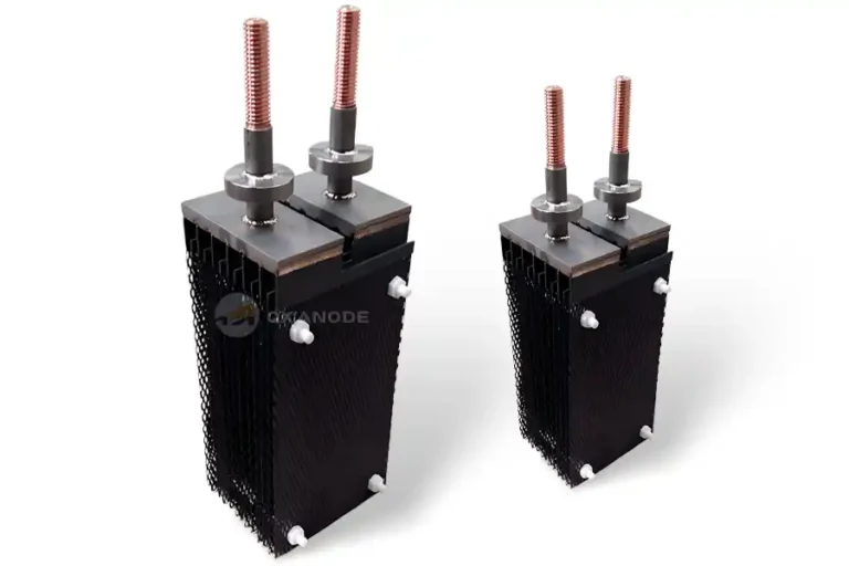
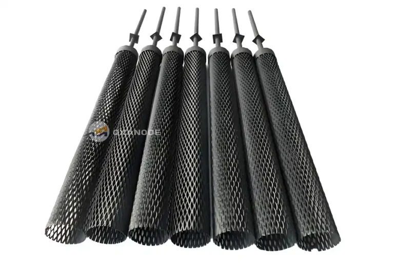
| Auxiliary anode | Discharges protection current into the seawater. | Platinized titanium (Pt layer 5 µm or thicker) or MMO coated titanium; polarization overpotential 0.3 V or lower at 100 A/m² |
| Reference electrode | Measures actual hull potential. | Solid-state Ag/AgCl, accuracy ±10 mV, service life 5 years or longer; mounted at least 2 m from any anode |
| Monitoring network | Verifies protection is uniform over the whole hull. | 5 to 8 reference electrodes spaced no more than 15 m apart; voltmeter input impedance 100 MΩ or higher, 0.01 V resolution |
Installation note: the blasted and painted area around each anode must meet coating thickness and quality requirements, otherwise current shorts through the coating and protection fails locally.
Why MMO coated titanium leads for auxiliary anodes
The auxiliary anode is the component that decides service life. Platinized titanium anodes should consume no more than about 1 g per ampere-year, and the anode is due for replacement once the platinum layer wears below 2 µm. MMO coated titanium anodes deliver comparable or better durability at high current density in seawater, with a mixed metal oxide layer fired onto a titanium substrate that resists the demanding polarity conditions of ICCP service. For anode selection, confirm the coating is qualified for continuous seawater duty at the specified current density, and check the mounting insulation before commissioning.
Two lessons from fleet service
Read the current together with the potential. On one 100,000 DWT tanker in the Indian Ocean, the ICCP anode current jumped suddenly from 80 A to 250 A while the protection potential held steady at -0.9 V. The crew suspected an anode short, but a short would have pulled the anode potential sharply down. The real cause was a grounding incident that stripped about 20 m² of bottom paint. Bare steel demands roughly 120 mA/m² of protection current, against 10 to 20 mA/m² for painted areas, so the system correctly raised its output to hold potential. Caught late, a bare patch like that can show visible rust within a month.
Over-protection is real damage, not a safety margin. On a container ship, a failed potentiostat let the protection potential drift down to -1.2 V. Three months later the docking survey found bottom paint blistered and detached over large areas, with hydrogen cracking in the exposed plate.
ICCP maintenance essentials
- Check panel readings every watch. Record potential and current values daily. Expect current swings alongside berthing and canal transits in confined waters; these are normal.
- Calibrate reference electrodes against standard solution once per voyage. Replace any electrode that drifts more than 20 mV.
- Measure anode insulation resistance every six months. It should stay above 10 MΩ.
- Track anode consumption. Replace platinized anodes once the platinum layer falls below 2 µm.
- At docking, inspect anode surfaces for scale. Clean with high-pressure fresh water only. Never scrape the coating with hard tools.
- If potential drifts positive beyond -0.8 V, check first for reference electrode fouling or damaged cable insulation. If current spikes while potential stays stable, look for hull coating damage or an anode short.
MGPS: Keeping Seawater Cooling Lines Clear
The fouling problem
Marine organisms that settle inside sea chests and cooling piping restrict flow, raise cooling water temperatures, and force main engine load reductions. Once established, colonies are expensive to remove. The MGPS prevents settlement rather than fighting established growth, which is why every seawater-cooled system benefits from one.
How an MGPS works
There are two working principles in common service.
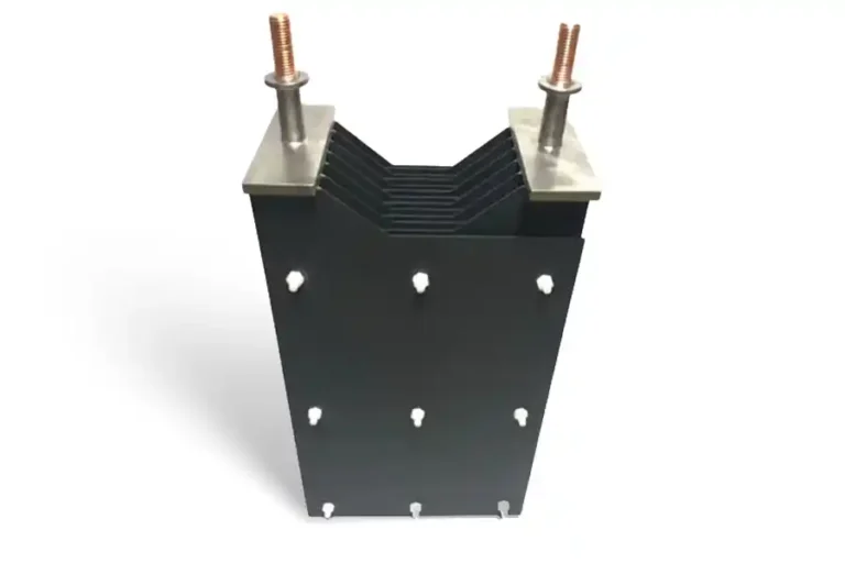
Anode dosing systems electrolyze copper, aluminum, or iron anodes mounted in the seawater stream. The current loop runs between the anodes and the hull, not between the anodes themselves. Copper anodes release trace copper ions, effective at levels around 2 mg/m³, that poison barnacle and mussel larvae before they can settle. Aluminum anodes release aluminum hydroxide floc that traps larvae mechanically, and the same floc lays down a thin film on pipe walls that adds a barrier against seawater corrosion. The anode grade matches the piping material: steel piping takes copper and aluminum anodes, while aluminum or copper piping takes iron anodes. Consumable anodes last 2 to 3 years and are renewed at docking.
Direct seawater electrolysis systems use a titanium plate, insulated from the hull, as the anode with the hull itself as the cathode. Electrolysis of the seawater generates oxidants in situ, the same chemistry behind electrochlorination, and no consumable metal is shipped or dosed.
Anode dosing systems face growing environmental scrutiny because they discharge copper and aluminum directly to sea, and both are non-renewable consumables. Several developed countries now discourage their use, which is why direct electrolysis designs are gaining ground in newbuilds.
Direct and indirect configurations
| Direct type | Indirect type | |
|---|---|---|
| Anode location | Inside the sea chest (sea valve box) | In a dedicated electrolysis tank in the engine room |
| Advantages | Simple structure, easy installation, low cost | Anodes replaced any time by isolating the tank valves, no drydocking needed |
| Drawbacks | Anode replacement requires drydocking; limited treated flow | Requires engine room floor space for the treatment tank |
| Analogy | Works like a full-flow electrolysis ballast water treatment system | Works like a side-stream electrolysis ballast water treatment system |
Two lessons from fleet service
Shut the system down before entering fresh water. A bulk carrier entered the Yangtze estuary, where salinity drops below 5 parts per thousand, without shutting down the electrolysis system. Fresh water conducts poorly, so the electrode overpotential climbed to 3.2 V, well past the 2.5 V safe limit. The system tripped on alarm after 3 hours. Inspection showed the electrode coating completely stripped and white magnesium hydroxide scale lining the piping. Replacing the electrodes and cleaning the line took 2 days.
Dosing must stay within limits. On a container ship, a controller fault pushed the copper ion concentration to 0.5 ppm. No fouling resulted, but the discharge exceeded limits at an EU port, exposing the operator to a potential fine of 120,000 euros under resolution MEPC.279(70).
MGPS maintenance schedule
| Interval | Task |
|---|---|
| Every 2 weeks | Flush reaction tank debris and scale. Isolate power and the seawater supply valve, then open the drain valve fully and use sea chest backflow to carry debris out. |
| Monthly | Wash the reaction tank, 10 to 20 minutes per electrode pair, at above-normal flow, one electrode side at a time. |
| Weekly on newbuilds, then quarterly | Check and re-torque electrode bolts with power isolated. Loose bolts cause poor contact and weak electrolysis. |
| Every 3 to 5 months | Descale electrodes. Drain the tank, lift the electrodes, remove scale, and sand back to bare metal. Trim any detached insulation tape, keeping the sound wrapping intact. |
| On over-voltage alarm (above 5 V) | Electrodes are likely consumed. Confirm piping material and fit the matching grade: steel piping takes copper-aluminum anodes, aluminum or copper piping takes iron anodes. |
| Continuous | Watch current and voltage. Normal operating current stays below about 1.5 A; unstable current points to poor contacts or heavy scale. |
Also inspect control box components (contactors, fuses, terminal tightness, burn marks), verify the cathode ground connection, and check seawater valves for free movement and sealing. Investigate any heavily corroded pipework against anode grade and dosing settings.
Shaft Grounding: The Electrical Firewall Around the Shaft Line
Where shaft voltage comes from
The propeller shaft connects the main engine to the propeller, and three current sources attack it at once:
- Electromagnetic induction. A moving hull cuts the earth’s magnetic field and induces voltage along the shaft. On a 100,000 DWT ship this can reach 0.3 V.
- Galvanic action. The bronze propeller and the steel shaft form a galvanic couple in seawater, driving current densities of 1 to 5 µA/cm².
- Stray current from power electronics. Harmonics from main engine variable frequency drives can push shaft voltage above 1 V.
The oil film in the bearings insulates the shaft from the hull, with resistance of 1 MΩ or higher, so these potentials build up instead of draining away. The result is electro-erosion of bearing white metal, with pits 0.05 to 0.5 mm across, spark discharge wear on shaft surfaces, and in bad cases interference with radar and GPS equipment.
How the grounding device works
A shaft grounding device gives the accumulated current a deliberate, low-resistance path to the hull. A slip ring rotates with the shaft, graphite brushes ride on it under controlled pressure, and a copper conductor of 50 mm² cross-section or larger carries the current to the hull grounding system. Total circuit resistance stays at 0.01 Ω or lower, which holds the shaft-to-hull potential difference at 30 mV or less, in line with ISO 19036:2016. Insulating components between the bearing housing and the hull, with resistance above 100 MΩ, block any parallel current path through the bearings.
Core components
| Component | Specification |
|---|---|
| Brush set | Electrographitic grade, resistivity 15 to 30 µΩ·m; 2 to 4 brushes per set; wear rate 0.1 mm per 1,000 hours or lower; brush holder contact voltage drop 0.2 V or lower |
| Slip ring | 316L stainless steel or hard chrome plated (chrome layer 50 µm or thicker); surface roughness Ra 0.8 µm or finer to limit brush wear |
| Insulation set | PTFE or ceramic, fitted between bearing housing and hull; better than 100 MΩ on a 500 V megger |
| Potential monitor | 1 kHz sampling rate; displays live shaft-to-hull potential difference, normally 50 mV or lower |
Two lessons from fleet service
Worn brushes destroy bearings. A 2-year-old bulk carrier ran with grounding brushes worn to a quarter of their original length and a slip ring filmed with oil and oxide. The shaft-to-hull potential difference sat at 170 to 250 mV for an extended period. When the main engine came apart, several main bearing shells showed white metal dissolved by electrical discharge and metal particles adhering to the journal, a textbook case of spark erosion feeding abrasive wear. The bearing renewal and journal repair ran past 2 million RMB, plus 15 days off hire.
Insulation ages too. On a container ship, the insulation set degraded to 50 MΩ. Part of the shaft current found a path through the bearing housing instead, and the resulting electrochemical attack corroded the stern tube seal. Seawater entered the stern tube and emulsified the lubricating oil, for a direct loss around 500,000 RMB.
Shaft grounding maintenance essentials
- Log the potential monitor every 4 hours. Keep the difference below 50 mV. Listen at the brush position: a steady hiss or crackle means discharge, which is not normal.
- Check brush length every 500 hours and replace brushes below one-third of original length.
- Monthly, clean brush holders with anhydrous ethanol and set contact pressure to 15 to 25 N/cm².
- Weekly, polish the slip ring with 800-grit paper to remove oil film and oxide. Measure the brush contact voltage drop; anything above 0.2 V means reseat the brushes.
- Monthly, megger the insulation set at 500 V. Replace insulators below 100 MΩ. Keep insulation faces free of oil; clean with acetone.
- Quarterly, record shaft voltage waveforms. Spikes above 0.5 V point to main engine drive harmonics, and the total harmonic distortion should be checked against a 5% limit.
Three Systems, One Defense
Installed together, the three systems cover each other’s blind spots:
- Corrosion coverage. ICCP protects the hull and propeller, with design current densities of 10 to 20 A/m² on the flat bottom and 25 to 30 A/m² near the waterline. The shaft grounding device protects the shaft line and bearings. Insulated coupling flanges, at 1 MΩ or better, keep ICCP current out of the shaft line so the two systems never fight each other.
- Power and protection in a loop. The MGPS keeps the cooling system effective and main engine temperatures at or below 85°C. The engine plant in turn supplies the DC power the ICCP system needs continuously and runs the grounding potential monitor.
- Compliance. ICCP has no chemical discharge, a properly tuned MGPS keeps copper discharge at or below 0.2 ppm, and the grounding device produces no waste. Together they align with MARPOL requirements and IMO G8 guidance.
On modern tonnage all three feed the central monitoring system. A sudden ICCP current rise triggers a GPS cross-check for grounding. An MGPS concentration alarm cuts electrolysis power and starts neutralization. A shaft potential anomaly locks main engine speed before bearings are damaged. The chain runs from early fault detection through automatic response to crew alert.
Need a custom anode for your process?
Send us your drawing or specs — we’ll quote within 12 hours.