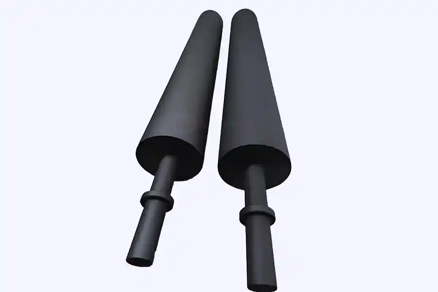
Cathodic electrodeposition · anode cells
IrO₂–Ta₂O₅ on Grade 1 titanium, built for the acidic, oxygen-rich anolyte inside a CED anode cell. Plates, tubes and mesh panels made to your drawing, with coating loading matched to the current density your tank actually runs.
10–40 g/m²
Coating loading
10–40 g/m²Coating loading20–30 g/m² is the usual band for CED duty
10–30 A/m²
Design current density
Continuous; 40 A/m² short-term
1–3 years
Typical service life
In a maintained cell with fluoride controlled
12 hours
Quote turnaround
Drawing or spec sheet in, priced offer out
Overview
What a titanium anode does in an e-coat tank
In cathodic electrophoretic coating the car body is the cathode. Paint particles carry a positive charge, migrate to the body and deposit there. The anodes hang in cells along the tank walls and close the circuit.
The reaction at the anode is water oxidation: 2H₂O → O₂ + 4H⁺ + 4e⁻. Oxygen leaves, acid stays. That is why the anolyte in a CED line sits at pH 2–4, and why the anode works in a harsher environment than anything else in the tank.
An MMO titanium anode is a dimensionally stable anode. The titanium substrate carries current to the surface; the mixed metal oxide coating does the electrochemistry. Titanium is not consumed by the reaction. The coating is, slowly, for as long as the anode is energised. Nearly every specification decision — coating chemistry, loading, current density, geometry — comes back to that one fact.
- Substrate
- Grade 1 titanium (ASTM B265, GB/T 3621); 1–3 mm sheet or 0.8–1.5 mm tube wall
- Coating
- IrO₂–Ta₂O₅, 70:30 molar, applied in multiple thermal decomposition passes
- Loading
- 10–40 g/m² of iridium and tantalum; 20–30 g/m² typical for CED
- Formats
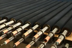
- Plate, tube, mesh and rod, made to drawing
- Connection
- Titanium stem or hanger; copper core for high-current rods
- Service life
- 1–3 years typical, set by current density, fluoride and cell maintenance
Cell design
An anode is only as good as the cell around it
Most premature failures we are asked to diagnose are cell problems that show up on the anode. These are the parts that decide whether a five-year plate reaches five years.
The membrane
A cation-exchange membrane separates anolyte from paint. Acid made at the anode stays inside the cell; phosphate and fluoride dragged in from pretreatment stay out of the bath. A torn membrane usually shows up as falling paint pH and a run of defects on the body weeks before anyone looks at the anode.The anolyte loop
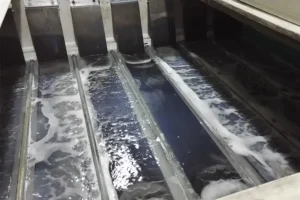
Circulated, filtered and cooled. Most lines hold pH 2–4 and conductivity below 700 µS/cm. Log both, and log fluoride separately: it is the most common reason a titanium anode dies years early.Anode-to-body distance
200–400 mm is the working range. Closer improves throw into cavities but concentrates current on the nearest panel. Further out evens film build and asks more voltage from the rectifier. Both ends of that trade-off are visible in film thickness surveys.Insulation and busbars
Stems, hangers and busbars are insulated from the frame. A stray earth path steals current and turns one plate into a hot spot; that plate usually fails first, at the hanger end, where the coating is hardest to keep intact.Coverage
Anodes on both sides, and on some lines along the floor, so roof rails and rocker panels see current. Uneven anode spacing is a routine cause of thin film in door apertures and wheel arches.Retrofit geometry
Replacing graphite or lead in an existing cell? Match the frame before anything else. Send the old drawing or the box dimensions. Mounting is usually the part that decides whether a retrofit fits without cutting the tank.
Coating selection
Why IrO₂–Ta₂O₅, and not ruthenium oxide
Ruthenium oxide is a chlorine catalyst. It belongs in chlor-alkali and hypochlorite plants, where the anode reaction is chloride to chlorine. An e-coat cell runs the other reaction.
There is almost no chloride in a CED anolyte. The reaction is oxygen evolution in acid, and ruthenium oxide dissolves quickly under it. Iridium oxide is stable in that duty, and tantalum oxide holds the iridium in a fine-grained matrix that slows the coating loss which eventually ends the anode’s life.
Loading is the other half of the specification. More grams per square metre buys more years, but past roughly 40 g/m² the gain flattens and each extra layer adds bake cycles that can introduce mud-cracking. For 10–30 A/m² CED duty, 20–30 g/m² is the band that balances life against cost.
Coating options for an e-coat anode cell, compared on the reaction they are built for.
Coating | Reaction it suits | Anolyte it tolerates | Fit for CED | What to watch |
|---|---|---|---|---|
IrO₂–Ta₂O₅ | Oxygen evolution | pH 2–4, sulfate, phosphate | Standard choice | Coating loss at high current density; fluoride attack through pores |
RuO₂–IrO₂ | Chlorine evolution, some oxygen | Chloride-rich, near neutral | Not recommended | Ruthenium dissolves quickly under oxygen evolution |
Pt/Ti | Oxygen or chlorine | Mild acid, neutral | Small cells, touch-up work | Platinum migrates at high oxygen-evolution potential; cost per square metre |
PbO₂ | Oxygen evolution | Strong acid | Legacy installations | Lead in the paint shop; being phased out on most new lines |
Graphite / 316L | — | — | Legacy | Sludge, dimensional wear, iron and carbon contamination of the bath |
Specifications
What we build, and the tolerances we hold
The values below describe what we make most often for CED lines. They are starting points, not a catalogue limit: loading and geometry are set per order against your line data.
Typical build for an automotive electrophoretic coating anode. Confirm final values on the quotation drawing.
| Parameter | Typical value | Notes |
|---|---|---|
| Substrate | Grade 1 titanium (ASTM B265, GB/T 3621) | Grade 2 on request; 1–3 mm sheet, 0.8–1.5 mm tube wall |
| Surface preparation | Degrease, blast, oxalic acid etch | Etch depth and rinse conductivity recorded per batch |
| Coating | IrO₂–Ta₂O₅, 70:30 molar | Multi-pass thermal decomposition, each pass baked |
| Coating loading | 15–40 g/m² | 20–30 g/m² typical for 10–30 A/m² CED duty |
| Current density | 10–30 A/m² continuous | 40 A/m² short-term; confirm against rectifier capacity |
| Cell voltage | 200–400 V DC | Set by line design and paint, not by the anode |
| Bath temperature | 25–45 °C | CED baths usually run 28–32 °C |
| Anolyte pH | 2–4 | Up to 6 on some lines; fluoride must be controlled either way |
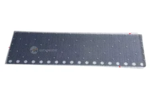
| Formats | Plate, tube, mesh, rod | Slotted, tabbed or drilled to suit your frame |
| Connection | Titanium stem or hanger | Copper core for high-current rods; leak tested before coating |
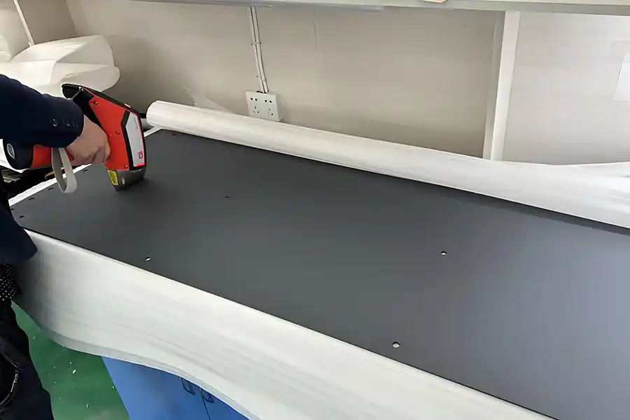
| Tolerance | ±0.5 mm on plate; ±0.2 mm on hole position | Measured on a sample from every batch |
| Expected life | 1–3 years | Driven by current density, fluoride and cell maintenance |
Most common
Plate
1–3 mm sheet, typically 300–1000 mm wide and up to 2000 mm long. Slotted or tabbed to drop into an existing frame. The default for car bodies and large panels.
Confined zones
Tube
1–3 mm sheet, typically 300–1000 mm wide and up to 2000 mm long. Slotted or tabbed to drop into an existing frame. The default for car bodies and large panels.
Most common
Plate
1–3 mm sheet, typically 300–1000 mm wide and up to 2000 mm long. Slotted or tabbed to drop into an existing frame. The default for car bodies and large panels.
Most common
Plate
1–3 mm sheet, typically 300–1000 mm wide and up to 2000 mm long. Slotted or tabbed to drop into an existing frame. The default for car bodies and large panels.