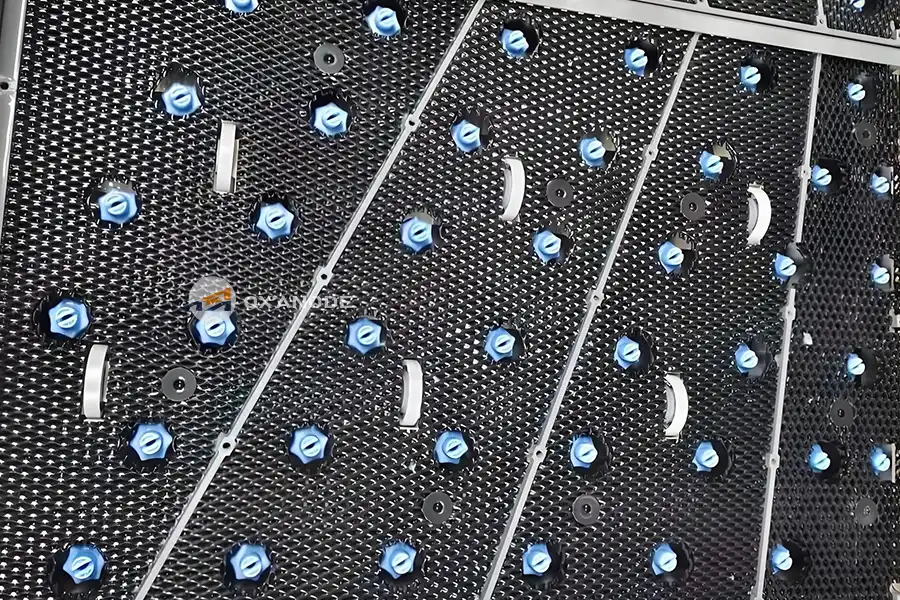
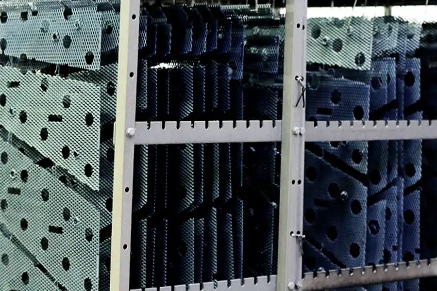
A horizontal copper plating line carries the panel flat, face up, on a conveyor. The anode sits above it and below it, a short fixed distance away, and it does not dissolve. That last point is the reason the whole line works the way it does.
Phosphorized copper anodes feed the bath as they corrode. Put them on a horizontal line and they change shape as they wear, drop sludge and nodules onto the panel, and move the anode-to-cathode gap while the run is in progress. So horizontal modules run insoluble anodes instead: a titanium substrate carrying a mixed metal oxide coating, most often IrO₂–Ta₂O₅. The anode keeps the geometry the process engineer set, and all the copper in the deposit comes from the electrolyte.
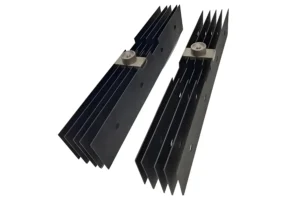
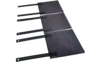
A titanium anode for PCB horizontal copper plating is an insoluble (dimensionally stable) electrode — a Grade 1 or Grade 2 titanium substrate carrying an IrO₂ Ta₂O₅ mixed metal oxide coating, mounted above and below the panel to evolve oxygen while holding a fixed anode-to-cathode gap in acid sulfate copper electrolyte.
Key takeaways
- Horizontal lines run insoluble anodes. Soluble phosphorized copper shifts the gap, sheds sludge, and cannot operate under reverse pulse.
- IrO₂–Ta₂O₅ is the coating for acid sulfate copper. Ruthenium-based coatings lose precious metal to volatile RuO₄ under sustained oxygen evolution.
- PCB anodes usually fail sooner than electrowinning anodes at comparable current density. Organic brighteners and levelers attack the coating. The current is not the limiting factor.
- Reverse pulse plating needs a reverse-current-tolerant formulation. Standard coatings lose adhesion under cathodic half-cycles.
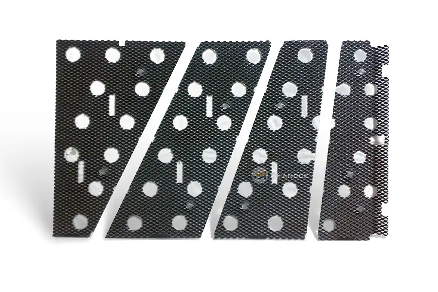
- Mesh is the standard form on horizontal modules. Open area, wire diameter and flatness govern both flow and current distribution.
- Track cell voltage, not calendar time. A sustained 15–20% rise over baseline at identical conditions means the coating is spent.
Horizontal plating and VCP: what the anode is actually asked to do
On a vertical continuous plating (VCP) line the panel hangs from a flight bar and passes through the bath upright. The anodes are fixed vertical plates on either side. On a horizontal conveyorized line the panel lies flat and travels through a series of short plating modules, each with anode banks above and below.
The two designs solve different problems, and the anode sits at the centre of the difference.
VCP is generally credited with better throwing power on very high aspect-ratio through-holes, and it handles thick, rigid boards well. Its known weakness is the dog-bone effect: copper builds up faster near the panel edge than at the centre, because the edge sees a shorter current path to the anode. Plants compensate with auxiliary anodes and current shields.
Horizontal plating puts every panel through the same anode bank in the same orientation, so panel-to-panel consistency is high and edge effects are easier to manage. The trade-off is that the anode-to-cathode gap is short and fixed by the module geometry. There is no room to compensate for a worn anode by moving it. The anode has to hold its shape.
Horizontal lines are the usual choice for thin cores, flexible and rigid-flex constructions, and boards that a vertical flight bar would bend or mark. If your line runs any of those, the anode specification matters more than it does on a conventional VCP line.
Why horizontal lines run insoluble anodes instead of copper
Four reasons, in the order they usually matter to a process engineer.
1. The gap has to stay put. Current distribution across a panel depends on the anode-to-cathode distance. A soluble anode dissolves unevenly — faster at the edges, faster where flow is highest — so the gap changes through the campaign. Throwing power drifts with it. A dimensionally stable anode does not move. What you set at commissioning is what you run in month thirty.
2. No anode sludge. Phosphorized copper anodes leave behind an insoluble film and, over time, nodules and debris. On a vertical line that debris falls to the bottom of the tank. On a horizontal line the panel is directly underneath the upper anode bank, and the gap is small. Debris that detaches lands on wet copper. The result shows up as pitting, roughness, and rejects on boards that plated correctly everywhere else.
3. No anode maintenance cycle. Soluble anodes need bags, periodic replacement, and dummy plating to condition new anodes before they go into production. Insoluble anodes need inspection. On a line running three shifts, that difference is measured in lost production hours.
4. Reverse pulse plating requires it. RPP and pulse-reverse waveforms run a cathodic half-cycle at the anode. A copper anode simply plates during that half-cycle and cannot function. An insoluble anode can — provided the coating is formulated to survive the reversal. More on this below, because it is where most specification errors happen.
The coating that works in acid copper — and the ones that do not
Acid sulfate copper is an oxygen-evolving environment. That single fact decides the coating.
In an acidic sulfate bath the anode reaction is oxygen evolution, and it runs at a high anodic potential. Under those conditions RuO₂ oxidises further to RuO₄, which is volatile. A ruthenium-based coating in this duty loses precious metal continuously and can fail in a fraction of its expected life. Ru-Ir coatings are the right answer for chloride and brine service — chlorine evolution, hypochlorite generation, chlor-alkali — and the wrong answer for acid copper. Do not let price pull you that way.
IrO₂–Ta₂O₅ is the industry standard for acid sulfate oxygen evolution. The two oxides do different jobs:
- Iridium dioxide catalyses the oxygen evolution reaction at low overpotential and, critically, stays put. Under high anodic potential IrO₂ does not form a volatile higher oxide, so the coating dissolves slowly rather than evaporating.
- Tantalum pentoxide is largely inert electrocatalytically but forms a dense, acid-resistant framework. It suppresses cracking, slows iridium dissolution, and shields the titanium substrate from anodic passivation.
Published work and industrial practice converge on roughly 70 mol% IrO₂ / 30 mol% Ta₂O₅ as the optimum for acidic OER — the best balance of activity and service life. A 65:35 formulation trades some life for cost. Higher iridium fractions buy life at rising cost, and iridium price moves with the market.
Coating | Environment it fits | Anode reaction | Why it fails in acid copper |
|---|---|---|---|
IrO₂ Ta₂O₅ (Ir Ta) | Strong acid, sulfate systems, sustained OER | Oxygen evolution | this is the correct choice |
RuO₂ IrO₂ (Ru Ir) | Chloride / brine, chlor-alkali, hypochlorite | Chlorine evolution | RuO₂ oxidises to volatile RuO₄; rapid precious-metal loss |
Platinized titanium (Pt/Ti) | Fluoride-free plating, general purpose | Varies | High cost; limited life at high current density |
PbO₂ / lead alloy | Cost-driven electrowinning | Oxygen evolution | Lead contamination of the deposit; heavy; shorter life |
Ir Ta versus platinized titanium
Both work in acid copper. The choice is usually economic.
Platinized titanium anodes carry a solid platinum layer and are the historical solution — several OEM horizontal lines were commissioned with them, and suppliers such as Umicore still market platinum-based insoluble anodes for PCB service. They perform well, and they cost more, both at purchase and at recoat.
MMO anodes use a fraction of the precious metal for the same duty. Published comparisons put Ir-Ta coatings below Pt/Ti on cost for oxygen-evolving service, with a lower oxygen evolution overpotential, which shows up as lower cell voltage and lower power draw at the rectifier. Where platinized titanium retains an advantage is at the upper end of current density and in certain specialised electrolytes.
If you are replacing Pt/Ti anodes in an existing horizontal module, the mechanical dimensions and connection design usually transfer directly. Send the drawing.
Why PCB anodes wear out faster than electrowinning anodes
This is the part most supplier literature skips.
An Ir-Ta anode in copper electrowinning at a few hundred A/m² routinely runs for years. An anode in PCB acid copper, at a comparable or even lower current density, often does not. The current density is not the difference.
The difference is the additive package. Acid copper for PCB work contains organic brighteners, levellers and carriers, plus chloride, all maintained within a narrow window. Those organics adsorb on the anode surface and are oxidised there. Peer-reviewed work on IrO₂–Ta₂O₅ durability in copper electroplating systems has shown that organic additives actively accelerate coating degradation — the mechanism is chemical and electrochemical attack on the active layer, not simple wear from charge throughput.
Three practical consequences:
- Do not extrapolate anode life from a different application. A lifetime quoted for electrowinning, cathodic protection, or copper foil is not transferable to PCB acid copper. Ask your supplier what their number is based on.
- Additive control is anode control. A bath running hot on brightener, or one where carrier breakdown products accumulate, will shorten anode life independently of anything the anode does. If anodes are failing early across a line, check bath chemistry before blaming the anode.
- Life is application-specific, and honest suppliers say so. For our Ir-Ta anodes we quote service life against your electrolyte, your current density, and your target — not as a headline number. Any supplier guaranteeing a fixed multi-year life for PCB acid copper without asking about your additive system is quoting marketing, not engineering.
Reverse pulse plating changes the anode specification
If your line runs RPP, pulse-reverse, or any waveform with a cathodic half-cycle at the anode, the coating specification changes.
Reverse and intermittent current reduces coating adhesion. The mechanism is straightforward: during the cathodic half-cycle the local chemistry at the coating interface shifts, and repeated cycling works at the bond between the oxide layer and the titanium substrate. Over time the coating can lift or spall — and once the substrate is exposed, titanium passivates to an insulating TiO₂ film, resistance climbs, and the anode stops carrying current where it stopped conducting.
What to specify:
- Tell the manufacturer the waveform. Not just “pulse plating” — the reverse current density, the reverse-to-forward charge ratio, and the frequency. These determine the formulation.
- Ask for a reverse-current-tolerant coating. Formulations differ. A standard DC-service coating is not automatically suitable.
- Cover the shutdown case. Plants with unreliable mains power or planned interruptions expose anodes to reverse current during decay. If that describes your line, say so in the inquiry.
Getting this wrong is expensive and slow to diagnose. The anodes look fine. Cell voltage creeps up over months. Uniformity drifts. By the time anyone connects it to the waveform, a full anode bank has been consumed.
How to tell an anode is nearing end of life
Ir-Ta coatings wear out gradually. Iridium dissolves at a slow, finite rate. Once active loading drops below a threshold, cell voltage climbs.
The most reliable indicator is not visual. It is a sustained voltage rise of 15–20% over baseline, measured under identical conditions — same current density, same temperature, same bath chemistry, same gap.
Set that up deliberately:
- Record baseline cell voltage per module at commissioning, with the operating conditions logged alongside it.
- Measure at fixed intervals under the same conditions. Trend it. A single reading means little; the slope means everything.
- Watch for uneven behaviour across a bank. One anode drifting while its neighbours hold suggests a local problem — poor connection, flow blockage, coating damage — not general wear.
- Inspect for spalling and passivation. Exposed titanium turns from metallic grey to a dull, insulating surface. Where you see it, that section is not plating.
Two other conditions shorten life below specification, and both are avoidable:
- Running above design current density. Pushing a module harder than the anode was rated for accelerates coating wear and raises bath temperature. Both feed each other.
- Fluoride in the electrolyte. Fluoride attacks the titanium substrate underneath the coating. Above trace levels, discuss substrate protection with the manufacturer before ordering. This is uncommon in acid copper but not unheard of where upstream treatments carry over.
Can a spent anode be recoated?
Usually yes, and it is normally cheaper than buying new. The titanium substrate is stripped, re-etched, and recoated. Whether recoating is worthwhile depends on substrate condition — if the titanium has been passivated or pitted, particularly from fluoride attack or prolonged reverse current, the substrate may not be reusable. Send photographs and the operating history with the recoating inquiry.
Specifications at a glance
| Parameter | Typical value for PCB horizontal copper plating |
|---|---|
| Coating system 涂层体系 | IrO₂–Ta₂O₅ mixed metal oxide, ≈70:30 mol Ir:Ta IrO₂–Ta₂O₅ 混合金属氧化物,摩尔比约 70:30 |
| Substrate 基体 | Grade 1 / Grade 2 commercially pure titanium, ASTM B265 / B348 1 级/2 级工业纯钛,ASTM B265 / B348 |
| Substrate thickness 基体厚度 | 1–3 mm plate; mesh wire diameter to module design 板材 1–3 mm;网材丝径依模块设计而定 |
| Primary anode reaction 主阳极反应 | Oxygen evolution in acid sulfate media 酸性硫酸盐介质中析氧 |
| Coating thickness 涂层厚度 | 5–20 µm, applied in multiple thermal-decomposition cycles 5–20 µm,经多次热分解循环施加 |
| Precious metal loading 贵金属载量 | ≈5–50 g/m², set by duty and target life 约 5–50 g/m²,由工况与目标寿命确定 |
| Cathode current density (acid copper) 阴极电流密度(酸铜) | Typically 1–8 A/dm² (10–80 A/m²), DC or pulse — additive-system dependent 通常 1–8 A/dm²(10–80 A/m²),直流或脉冲——取决于添加剂体系 |
| Bath temperature 镀液温度 | 20–60 °C continuous (acid copper commonly runs at the lower end) 连续运行 20–60 °C(酸铜通常在低端区间) |
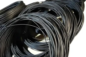
| Common forms 常见形态 | Mesh grid, plate, corrugated profile, machined parts to drawing 网状栅格、板材、瓦楞型材、按图机加工件 |
| End-of-life criterion 寿命终点判据 | Sustained 15–20% cell voltage rise over baseline at identical conditions 相同工况下槽压相对基线持续上升 15–20% |
| Service life 使用寿命 | Application-dependent; shorter in PCB acid copper than in electrowinning at similar current density, because of additive attack 依应用而定;因添加剂侵蚀,在 PCB 酸铜中短于相近电流密度下的电积工况 |